What is IC number for phase lock loop?
What is IC number for phase lock loop?
IC 565. The purpose of each pin is self-explanatory from the above diagram. Out of 14 pins, only 10 pins (pin number 1 to 10) are utilized for the operation of PLL.
What is a phase locked loop used for?
Phase locked loops are closed-loop feedback systems consisting of both analog and digital components including a voltage controlled oscillator. They are used for the generation of an output signal the frequency of which (or that of a signal derived from it) is synchronized (or locked) to that of a reference input.
What is IC LM565?
The LM565 is a general-purpose PLL or phase-locked loop IC which includes a constant, extremely linear VCO (voltage controlled oscillator) for less deformation FM demodulation & a phase detector with double balanced & superior carrier control.
What is PLL IC?
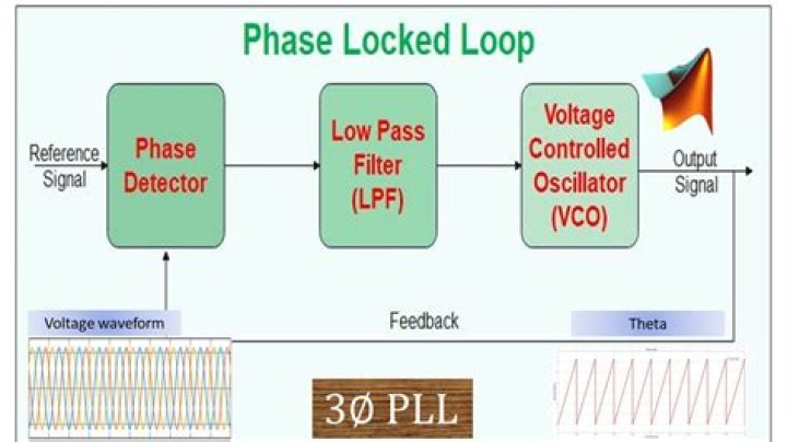
IC phase locked loops (PLL) are closed-loop frequency controls that are based on the phase difference between the input signal and the output signal of a controlled oscillator. An IC phase-locked loop generally consists of a phase detector, a loop filter, voltage controlled oscillator (VCO) and an amplifier.
What are features of IC 565?
Features of IC 565:
- Extreme stability of center frequency typically 200ppm.
- Wide range of operating voltage ±6V to ±12V.
- Very high linearity of demodulated output typically 0.2%
- Centre frequency of VCO is programmable by means of resistor, capacitor or voltage.
- TTL compatible square wave output.
What is the principle of PLL?
The input signal is directly proportional to the output frequency of the VCO (fo). The input and output frequencies are compared and adjusted through the feedback loop until the output frequency is equal to the input frequency. Hence, the PLL works like free running, capture, and phase lock.
What is the use of PLL in microcontroller?
PLLs are finding increasing usage in microcontrollers to manipulate the frequency of clock signals. This can allow certain sections of the microcontroller to run faster than others, or to run the microcontroller at a clock frequency faster than the oscillator itself.
What are the 3 working modes of PLL *?
Both the input frequency and output frequency are compared and adjusted through feedback loops until the output frequency equals the input frequency. Thus the PLL works in these stages – free-running, capture and phase lock.
Which pin is used for output in IC 566?
LM565 is a 14 pin device and the function of each pin is stated below….Pin Configuration.
| Pin | Name | Function |
|---|---|---|
| 1 | -Vcc | Negative power supply input pin |
| 2 | Input | Phase detector input pin (FM signal input) |
| 3 | Input | Phase detector input pin (FM signal input) |
| 4 | VCO output | VCO (Voltage Control Oscillator) output seen at this pin |
What is phase-locked loop PDF?
A phase-locked loop is a feedback system combining a voltage controlled oscillator (VCO) and a phase comparator so connected that the oscillator maintains a constant phase angle relative to a reference signal.
Which circuit is block in PLL?
Phase comparator / detector: As the name implies, this circuit block within the PLL compares the phase of two signals and generates a voltage according to the phase difference between the two signals. This circuit can take a variety of forms. . . . .
What is the IC number op amp?
The operational amplifier or op amp is an electronic device or element, that behaves like a voltage controlled voltage source. An op amp is a complex electronic device, which consists of resistors, capacitors, transistors and diodes. Most commonly available and used op amp IC is IC 741.